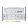

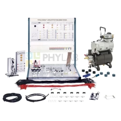
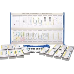
The composition of the set:
Panel Transmitter -1 pc:
Broadband frequency
TTL and CMOS input
Panel Receiver-1 piece:
Broadband frequency
TTL and CMOS output
Panel Synchronous switch P/S -1 pc:
8 bit data
External and internal data source
LEDs for status indication
Panel Synchronous S/P switch -1 pc:
8-bit data.
LEDs for status indication
Panel Asynchronous switch P/S -1 pc:
8-bit data.
External and internal data source
LEDs for status indication
Panel Asynchronous switch S/P -1 pc:
8 data bits
LEDs for status indication
Analog-to-digital converter panel-1 piece:
Switching on the function of the type of ADC under study
0 to 5 volt conversion range with 8 bits of digital data output
LEDs for indicating the input and output status of the conversion
Digital-to-analog converter panel-1 piece:
Turning on the function of the type of digital-to-analog conversion under study
The module includes a 20 mV LSB reference voltage source and 256 combinational digital logic circuits.
LEDs for indicating the input and output status of the conversion.
Voltage/frequency converter panel-1 piece:
Input voltage: 0-5 VDC
Output frequency: 20 – 20 kHz
Frequency average: 100 kHz
Frequency/voltage converter panel-1 piece:
Input frequency: 20 – 20 kHz
Output voltage: 0 – 5 VDC
Frequency average: 100 kHz
Panel Audiomodule 2 pcs:
Purpose: The module can be used as a speaker or microphone.
Panel pulse generator-1 piece:
Direct output or inverted output
Clock frequencies provide 2 ranges: 2 – 300 Hz and 100 – 16 kHz
Generate positive or negative edge using the switch
Single actuation available
Voltage input: +15 V AND -15 VDC
Power supply 1 pc:
Input voltage: 220 V AC, 50 Hz
Output Voltage:
+15VDC, 1A
+5V DC, 1A
-15VDC, 1A
Plastic fiber optic cable, length 50 cm – 1 pc.
Connecting jumper – 60 pcs.
Connecting wire 50 cm, blue – 40 pcs.
Guide to experiments -1 pcs.
Frame, width at least 1200 mm 1 pc.


 Русский