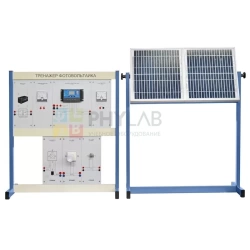
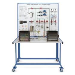
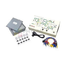
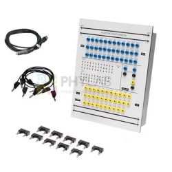
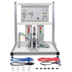
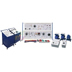
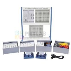
The simulator is designed to teach the fundamental concepts of single-phase and three-phase transformers and to familiarize you with their characteristics.
The panel modules show graphic diagrams and technical data of the transformer.
The stand is equipped with basic measuring equipment for transformers (voltmeter, ammeter).
There is a current protection device suitable for providing ground-fault protection. Circuit breaker tripping current at fault 30 mA with indicator lamp.
All inputs and outputs on each panel are equipped with protected connectors and protected connection wires and 4 mm cross-connectors.
A complete step-by-step guide to the experiments is included.
The composition of the set:
Three-phase power supply with FCCB
4-pole switch
Fault current circuit breaker 30 mA
Phase control lamps L1, L2, L3
Main cable with plug
Single phase power supply
2-pole switch
Fault current circuit breaker 30 mA
Phase control lamp L1
Main cable with plug
Single-phase AC power supply
Power supply voltage : 230 V, 50 Hz.
Output : 0 – 240 VAC
Current : Max. 5A
Power Max. 1 kVA
Single-phase transformer with EI core
Primary : 230 V, 50 Hz
Secondary : 2 x (0 – 115) V
Rated current : Max. 0.9A
Power : Max. 200 VA
Single-phase transformer with toroidal core
Primary : 230 V, 50 Hz
Secondary : 2 x (0 – 115) V
Rated current : Max. 0.9 A
Power : Max. 200 VA
Single-phase automatic transformer
Primary : 230 V, 50 Hz
Secondary : 115 V; 1.8 A/; 240 V; 0.9 A
Rated current : Max. 0.9A
Power Max. 200 VA
Three-phase transformer
Suitable for : Star to star connection
Star-delta connection
Star-delta connection
Star-zigzag connection
Primary: 3 x 230 V / 400 V, 50 Hz
Secondary: 3 x 2 x (0 – 115)
Rated current: Max. 0.9A
Power: Max. 600 VA
Load
Circular rheostat for transformer load.
Resistance: 470 Ohm
Power: 300W
Single-phase digital power meter
Power meter, main power supply 220V AC. Can be used to measure voltage, current, frequency, power in VA, W, Reactive power, Power Factor.
The display is a 4-digit LED.
Four-channel isolation amplifier
Channel: A, B, C, D
Input voltage: max. 450 В
Measuring ranges: 1 : 1, 1 : 10, 1 : 100
Overload indication with LEDs
Set of connecting wires:
Safety connecting wire 100 cm – 18 pcs.
Safety connecting wire 50 cm – 4 pcs
Safety connecting wire 30 cm – 15 pcs
Experiment manual – 1 pc


